Blog Post 2: Eurorack Accessories and Laser Cutter
I have been building a Eurorack modular synthesizer system, diving deep into its many sonic possibilities. “Eurorack” is a standard for control voltage and module width/depth developed by Doepfer and not a proprietary format, leading to modules of various origin and function to operate harmoniously within any number of custom setups.
However, despite a market occupied by hundreds of manufacturers of synthesizer modules, the modules are very expensive relative to their modular function, especially when compared to other digital synthesis solutions – $180 could buy an entire suite of synthesis software to make any sound imaginable on a personal computer, but in Eurorack it’s a reasonable price to pay for a module that simply outputs a bass drum sound.
Fortunately, there is also an open-source and DIY attitude among the modular community’s niche enthusiasts. In addition to releasing assembly-required kits, many module builders release circuit schematics and even sell naked printed circuit boards of their specialized units. So, once the basics of a modular system are in place, with a bit of electronics assembly skill and significantly less money, an enthusiast can expand their system at a fraction of the cost of buying an out-of-the-box module.
I decided to not attempt a complex kit for my first attempt at assembling a Eurorack module, but rather the simplest module commonly found in many setups: the passive multiplier! Patch cables usually send voltage only between two terminals on synthesizers, but a multiplier splits the signal to allow, for example, a control voltage envelope to control both an amplifier and a filter. Fortunately, passive multipliers need no external power, they just unite multiple 3.5mm jacks to mirror the same voltage. Because of this, they can also be very narrow. I decided to make a multiplier with 2 circuits of 3 connected jacks.
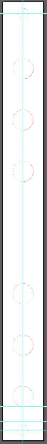
First, I found the specifications from Doepfer for Eurorack modules that all manufacturers follow, and made a template for a laser-cut panel in Illustrator. I used a 2 HP width, with screw holes in the center of the panel rather than at the 4 corners. I could use this template, adjusting the width for different HP, for other future panels.
I also found the specification for the particular 3.5mm jacks by Thonkiconn I used so I could cut precise holes to seat the terminals. Though Doepfer (and many manufacturers) recommend anodized aluminum for their panel fronts, I used 1/16” clear acrylic sheet I had bought for other projects.
I outlined these cuts in 0.001 pt width red in Illustrator to tell the laser to cut out these holes. I’d have a serviceable panel with this design, but I decided to add some functional and decorative elements.
I “titled” it in the middle by writing "mult" in a fun font. Guidelines and numbers above the two groups of three holes indicate there are two separate multiplier circuits. Both of these are 0.001 pt blue strokes to indicate “deep cut” mode to the laser cutter. They turn out to be a little deeper engraved rather than just a light scuffing of the surface.
I also added some decorative lines that recall noisy waveforms by creating a rectangular grid and distorting it using Illustrator effects and a variable-width stroke. These ideally would just decorate the clear panel, and be distinct from the text/lines between outlets by being a shallower cut into the material. I left them black to be engraved normally.
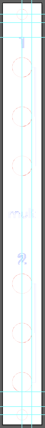
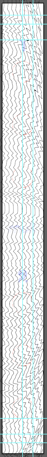
From left to right: cuts, text/function lines, decorative pattern
When the laser cutter finished, the deep engraving and cuts worked, but the noisy lines were not visible. Perhaps the 0.05 strokes were too thin in the middle using the stroke profile (bulbous at both ends) to register on the material, especially cutting through the thin paper that comes on top of the raw panels.

The cut panel with jacks, ready to install
I made sure the cut panel could fit into my rack by screwing it into the rails. Then, I unscrewed the nut off one of the 3.5mm jacks and put it behind the panel, pushing out. It fit snugly into the hole without forcing. Even though the decorative lines didn’t work out, I’m happy that I got the measurements right on the template.
I then seated and oriented all of the jacks in the same direction.

Seated jacks, ready to solder.
I soldered the pins of the jacks together with wire connecting the ground and positive pegs respectively in series.

Soldering hookup wire between the jacks
I tested continuity among each side using my multimeter, and then plugged in a patch cable to multiply the output of my MakeNoise 0-coast synthesizer clock trigger, a very useful function I really needed!

Sending the clock output to the multiplier, and then back into the synthesizer to trigger both "slope" and "cycle" circuits.
As a bonus, I also cut out a 16 HP "blind panel" to cover some unused space in my rack. This time I used a pattern I generated in Processing and vectorized in Illustrator to cover it, and cut the whole thing in "deep engrave" mode. This was also a test for a future project using similar designs on acrylic panels.

The blind panel in place.
I also cut out of thick fiberboard a tabletop rack to hold all my patch cables. Nice!

I think the laser was a little too strong or the material too thick, you can see the significant burning and carbon left on the inside fingers of the holder.